
Power Ground Water
0.00
Free shipping for orders above 100 USD.
We customize and ship all orders from our NYC studio. Customized and regular orders usually ship within 1 business day.

A series of "physical lecture notes" present a low level entry point into the material of electronics. This perspective is usually reserved for engineers, and obfuscated within the sealed boxes of our phones and computers. Here we consider the material of computation as just physical stuff, where the base material unit is the transistor and we build up from there.
This piece was originally developed in 2020 to support the Poetic Hardware curriculum at SFPC, a course which supports artists in their use of technology as a tool within a creative practice. It is now in its 3rd iteration.

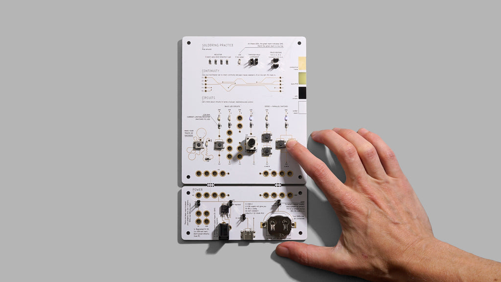
With PCB 01, we introduce the anatomy of a PCB, practice soldering surface mount and through hole components, edit PCB traces with a utility blade and learn continuity with a multimeter.
The lower part is a snap-off power supply module that offers different ways of powering projects. And finally in the middle portion are several basic LED, resistor and switch circuits.

PCB 02 presents the electronic switch. Here we play with a relay as an electronically controlled switch and signal amplifier, and then also introduce the N-MOS and P-MOS transistor as a version of the electromechanical relay as a solid-state device (with no moving parts). From here we use CMOS (complementary metal oxide semiconductor) logic, to build logic gates from transistors. These are the fundamental building blocks of all functional computers and CMOS logic is the logic family in use today.

PCB 03 is the first step into encapsulating the transistor. We begin the process of encapsulation as the transistors which form NAND logic gates are neatly packed into the 4093 integrated circuit (IC). We choose the NAND gate because it is one of the universal logic gates, from it you can create all other logic gates. From here we use NAND gates to build an inverter, AND and XOR gate and then wire them as a half-adder, illustrating first stage in a functional binary calculator.

PBC 04 introduces feedback + memory. Here we explore what happens when we connect the output to the input of a logic gate. All of a sudden the present state of a circuit, depends not on the state of its inputs, but on its previous state. We begin considering circuits as time-based.
The first circuit at the top clocked 1-bit memory circuit made from a d flip-flop. This one's a personal favorite and inspired 1bit 1hz cpu, from way back. The middle circuit wires the d flip-flop as a binary counter, which is also a divide-by-2 circuit. The last circuit uses a 4013 IC as a decade counter.

PCB 05 is all about time. Again using feedback to build oscillating circuits. Here we have a relay oscillator, where oscillation speed is limited by a physical mechanism. The middle row has a series of schmitt-trigger inverter oscillators. These oscillations are visualized both visually and aurally. The intention was to keep the oscillations within a scale most can perceive with un-augmented senses. And finally a 555-timer circuit set around the 1hz frequency.

PCB 06 is a circuit of a barebones arduino. The idea behind this is to show the necessary components to incorporate a programmable microcontroller in a project. It is helpful as a jumping off point for those wanting to build their own microcontrollers and who are unsure where to start.
1bit memory.
The input [lower indicator LED/switch] gets registered to an output [upper indicator LED] only on the low->high clock [left side switch] transition.
REVIEWS